
What Are The Four Types Of CAD Software?
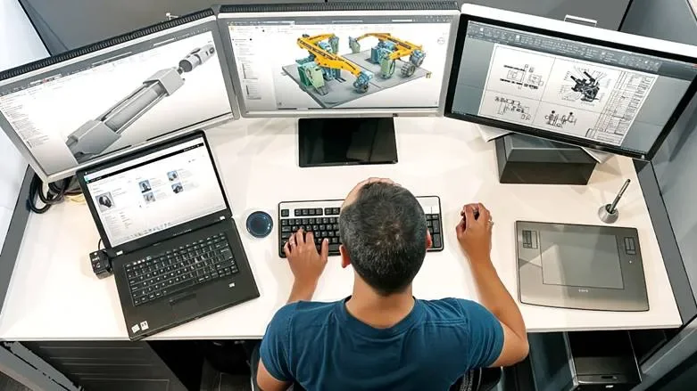
What Are The Four Types Of CAD Software? The four practical categories are 2D drafting CAD, 3D modeling CAD, parametric mechanical CAD, and specialized CAD systems. These categories help buyers match software to real deliverables: drawings, 3D models, mechanical assemblies, construction documents, CNC programs, simulation-ready geometry, or 3D printing files.
The categories can overlap, but they give a clear starting point for choosing the right tool. ProSoftStore helps CAD buyers compare software by workflow, output, and licensing needs instead of choosing only by a familiar product name.
Quick Check
Compare cad software programs at ProSoftStore before choosing between drafting tools, 3D modeling platforms, parametric CAD, and specialized CAD systems.
What Are The Four Types Of CAD Software?
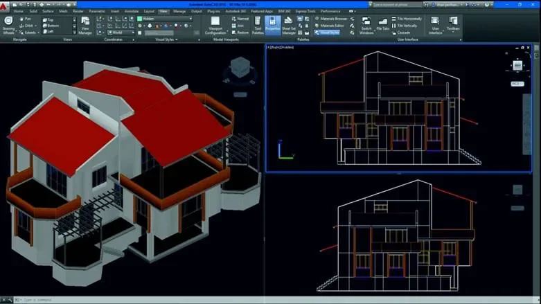
What Are The Four Types Of CAD Software? A useful buyer-focused answer is: 2D CAD, 3D CAD, parametric CAD, and specialized CAD systems. Autodesk describes CAD software as technology used to design in 2D or 3D, apply precise measurements, and generate documentation for manufacturing or construction. PTC describes Creo as a parametric 3D CAD platform with direct, parametric, and surface modeling, plus simulation, manufacturing, and data-management capabilities. Mastercam describes CAD/CAM software as supporting CNC machining operations such as milling, turning, 5-axis machining, mill-turn, Swiss machining, wire EDM, and router programming.
| CAD type | Main purpose | Common output | Best fit |
|---|---|---|---|
| 2D CAD | Drafting, layouts, dimensions, annotations | DWG drawings, PDFs, plans, details | Technical drawings, construction, fabrication |
| 3D CAD | Digital 3D model creation | Solids, surfaces, meshes, printable files | Product concepts, prototypes, visualization |
| Parametric CAD | Controlled feature-based design | Parts, assemblies, model-driven drawings | Mechanical design, product development |
| Specialized CAD systems | Industry-specific CAD workflows | CAM files, BIM data, simulation geometry, cloud models | CNC, architecture, CAE, direct editing |
The best category depends on the work. A floor plan, 3D printed bracket, machine assembly, CNC program, and simulation model should not be treated as the same CAD problem.
Type 1: 2D CAD Software
2D CAD software is used for drafting, drawing, detailing, layouts, dimensions, annotations, and technical documentation. Autodesk describes AutoCAD as a professional design and drafting tool used in architecture, construction, engineering, and manufacturing, with precise 2D and 3D sketches that include dimensions, measurements, and tolerances.
This type of CAD is useful when the final deliverable is a sheet, plan, detail, drawing package, or DWG file. It is often used for architectural drawings, construction details, electrical layouts, shop drawings, mechanical part drawings, fabrication layouts, and technical documentation.
For buyers comparing drafting tools with mechanical design tools, the drawing-first versus part-first CAD workflow helps explain why 2D documentation and 3D product modeling serve different needs.
Common Uses of 2D CAD
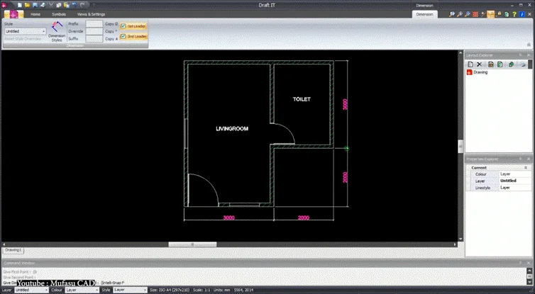
2D CAD is strongest when the design must be communicated through clear drawing sheets. It supports lines, arcs, hatches, dimensions, notes, layers, layouts, title blocks, viewports, and plotted output.
| 2D CAD use | Why it fits |
|---|---|
| Floor plans | Clear layout and dimension control |
| Construction details | Notes, callouts, sections, and scales |
| Electrical layouts | Plan-based symbol and routing documentation |
| Fabrication drawings | Part dimensions and production notes |
| Site plans | Scaled location and layout communication |
| Shop drawings | Installation and fabrication reference |
| Technical diagrams | Measured visual explanation |
2D CAD remains important because many teams still review, quote, permit, fabricate, and build from drawings. Even when 3D models exist, drawing sheets often remain part of approval, production, and archive workflows.
For documentation setup, the title block data and sheet-control basics are useful because clean CAD drawings need more than geometry; they need drawing numbers, revision fields, issue dates, and approval information.
Type 2: 3D CAD Software
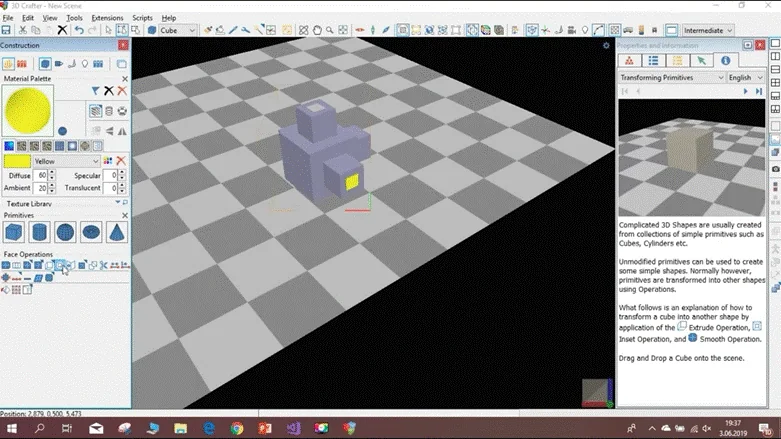
3D CAD software is used to create three-dimensional geometry. It may support solid modeling, surface modeling, mesh modeling, direct modeling, visualization, rendering, product previews, and sometimes manufacturing or simulation workflows. Autodesk says 3D CAD software is used across product design, manufacturing, architecture, and construction because it helps users visualize designs, simulate performance, and prepare models for fabrication, 3D printing, or construction.
3D CAD is useful when a user needs to understand shape, fit, volume, clearance, form, assembly structure, or printable geometry. It gives teams more spatial information than a flat drawing can provide.
For buyers deciding between general 3D modeling and engineering-grade design software, the modeling-output selection framework can help separate visual models, CAD models, printable models, and product design models.
Common Uses of 3D CAD
3D CAD can be used for product concepts, printed parts, architectural massing, mechanical components, industrial design, fixtures, prototypes, customer presentations, and early manufacturing review.
| 3D CAD use | Why it fits |
|---|---|
| Product concepts | Shows form, size, and proportions |
| Printable parts | Creates model files for slicers |
| Mechanical components | Supports fit and clearance checks |
| Enclosures | Helps plan walls, openings, and mounts |
| Visualization | Communicates design intent |
| Prototypes | Supports early test models |
| Surface design | Helps create complex exterior forms |
3D CAD is not automatically better than 2D CAD. It is better when the output requires spatial understanding, model export, geometry review, assembly planning, or physical prototyping. If the job is only a simple flat drawing, 2D CAD may be faster.
For printable models, the low-cost printable CAD workflow can help buyers decide when simple 3D modeling is enough and when stronger CAD control is needed.
Type 3: Parametric CAD Software
Parametric CAD software controls geometry through dimensions, constraints, features, relationships, and design intent. PTC describes Creo as a parametric 3D CAD system that supports product development with integrated design, simulation, and manufacturing functions.
Parametric CAD is valuable when a design will change. If a hole pattern, shaft diameter, bracket length, wall thickness, mounting face, or assembly relationship changes, the model can update through parameters instead of being rebuilt manually.
This type of CAD is common in mechanical engineering, machine design, tooling, product design, equipment design, fixtures, and manufacturing workflows.
For buyers comparing mechanical CAD platforms, the history-based mechanical design comparison helps explain why design intent, assemblies, and model-driven drawings matter.
Why Parametric CAD Matters
Parametric CAD matters because engineering design is rarely fixed on the first version. Product requirements change. Suppliers change. Manufacturing feedback arrives. A customer asks for a variant. A part needs to be stronger, lighter, cheaper, easier to machine, or easier to assemble.
A parametric model can preserve the relationship between sketches, features, dimensions, parts, assemblies, and drawings. This makes the workflow more controlled than repeatedly editing disconnected geometry.
| Parametric CAD capability | Practical value |
|---|---|
| Sketch constraints | Keeps geometry controlled |
| Feature history | Tracks how the model was built |
| Dimensions as variables | Makes edits faster |
| Assemblies | Connects parts into products |
| Model-driven drawings | Updates documentation from the model |
| Configurations or variants | Supports product families |
| Engineering change control | Reduces manual rebuilds |
Parametric CAD is often more structured than simple 3D modeling. That structure can be slower at first, but it helps when products require revisions, assemblies, and manufacturing documentation.
Type 4: Specialized CAD Systems
Specialized CAD systems are built for specific workflows or industries. This category includes CAD/CAM software, architectural CAD, BIM-connected workflows, direct modeling, simulation-prep CAD, electrical CAD, cloud CAD, additive manufacturing design tools, and reverse-engineering tools.
Mastercam is an example of specialized CAD/CAM software because it covers CNC machining operations such as milling, turning, 5-axis machining, mill-turn, Swiss machining, wire EDM, and router programming. Ansys SpaceClaim is another specialized example because Ansys describes it as a 3D modeling tool for geometry preparation that helps engineers get to simulation sooner.
Specialized CAD is usually chosen when general drafting or modeling is not enough. A CNC programmer, simulation analyst, architect, mechanical engineer, product designer, and construction team may all need CAD, but not the same CAD system.
For buyers comparing CAD and machining workflows, the CNC toolpath preparation workflow gives helpful context.
Specialized CAD Examples
Specialized CAD can be grouped by the problem it solves. The software may still create or edit geometry, but the workflow target is more specific.
| Specialized CAD type | Main use |
|---|---|
| CAD/CAM | CNC programming, toolpaths, machining |
| Architectural CAD | Building plans, details, residential layouts |
| BIM-oriented CAD | Building data and coordination workflows |
| Direct modeling CAD | Fast imported geometry edits |
| Simulation-prep CAD | Geometry cleanup before CAE |
| Additive CAD | Lattices, print-ready structures, lightweighting |
| Electrical CAD | Circuits, panels, wiring, harness workflows |
| Cloud CAD | Browser-based collaboration and version control |
For buyers comparing product geometry cleanup, the imported geometry preparation method helps explain why direct modeling and simulation-prep CAD differ from traditional feature-based design.
2D CAD vs 3D CAD
2D CAD and 3D CAD are often compared, but they answer different questions. 2D CAD asks, “What should this drawing show on a sheet?” 3D CAD asks, “What is the shape, volume, and form of this object?”
2D CAD is usually better for straightforward drawings, diagrams, layouts, and sheet-based documentation. 3D CAD is better when the user needs to check fit, view an object from multiple angles, create a physical prototype, or export a model.
| Workflow question | Better CAD type |
|---|---|
| Do I need a floor plan or detail sheet? | 2D CAD |
| Do I need a printable object? | 3D CAD |
| Do I need drawing annotations and title blocks? | 2D CAD |
| Do I need to check part fit? | 3D CAD |
| Do I need a simple DWG layout? | 2D CAD |
| Do I need a product model? | 3D CAD |
For visual modeling and drafting differences, the concept-modeling and drafting tool roles can help buyers choose by output.
Parametric CAD vs Direct Modeling
Parametric CAD and direct modeling are both 3D workflows, but they use different editing logic. Parametric CAD relies on design history, dimensions, constraints, and relationships. Direct modeling edits geometry more directly, which can be useful when imported files do not have usable feature history.
Ansys documentation describes SpaceClaim Direct Modeler as a direct modeling application, unlike history-based parametric applications. That distinction is useful for buyers because product designers and simulation analysts may need different editing methods.
Parametric CAD is usually better when the team owns the product design and expects controlled revisions. Direct modeling is often useful when the team receives outside CAD, needs fast cleanup, or wants to prepare geometry for simulation or manufacturing review.
CAD Software for Architecture
Architecture workflows often need plans, elevations, sections, details, schedules, drawing coordination, and building-specific documentation. A simple 3D model may not be enough if the final output needs construction documents.
Architectural CAD may focus on walls, doors, windows, rooms, drawing sets, dimensions, layouts, and plan-based documentation. Some tools are more visual, while others are more documentation-focused.
For building design decisions, the residential plan documentation pathway helps buyers compare building-focused CAD workflows instead of treating every CAD tool as general-purpose software.
CAD Software for Mechanical Engineering
Mechanical engineering workflows often need parametric models, assemblies, constraints, drawings, revisions, materials, tolerances, product variants, and manufacturing handoff. This is where parametric CAD and advanced mechanical CAD systems become more important.
A simple 3D modeling tool may create a shape, but mechanical CAD must support design intent and repeatable updates. That becomes important when parts interact, assemblies must move correctly, or drawings must update with the model.
For advanced engineering CAD context, the high-end CAD capability threshold can help buyers decide when a stronger product-development CAD system is justified.
CAD Software for Product Design
Product design can use several CAD categories at once. Early concept work may use general 3D modeling. Detailed engineering may use parametric CAD. Imported model cleanup may use direct modeling. Manufacturing preparation may use CAD/CAM.
A product workflow may begin with a concept, move into parametric design, produce drawings, pass through simulation, and then reach manufacturing. Each stage has different software needs.
This is why ProSoftStore helps buyers compare cad software systems by deliverable. The right product design setup depends on whether the team needs drawings, 3D models, assemblies, simulation, 3D printing, or machining output.
CAD Software for 3D Printing
3D printing workflows usually need a 3D model before slicing. CAD creates the model; slicer software prepares it for the printer. A beginner may use a simple modeling tool, while a mechanical user may need parametric CAD for fit, tolerances, and design revisions.
For workflow clarity, the model creation and slicer handoff explains why CAD software and 3D printing software are not the same.
If a user expects a printer bundle to include full CAD capability, the printer package design-tool reality can help set realistic expectations.
CAD Software for Manufacturing and CNC
Manufacturing workflows may need both CAD and CAM. CAD defines the part or design geometry. CAM prepares toolpaths and machining operations. A drawing or model may describe what the part should be, but CAM defines how the machine will cut it.
Mastercam’s official materials describe CAD/CAM coverage across CNC milling, turning, 5-axis machining, mill-turn, Swiss machining, wire EDM, and routing. That makes CAM a specialized software category, not a direct replacement for drafting CAD.
For shops reviewing CAM update cycles, the CAM version-change evaluation process can help compare production-focused software updates.
CAD Software for Simulation and Analysis
Simulation and analysis workflows depend on geometry, but they are not the same as drafting. Simulation-prep CAD may simplify models, remove small details, repair gaps, prepare fluid volumes, or organize geometry before analysis.
Ansys SpaceClaim is positioned around geometry preparation and direct modeling so engineers can get to simulation sooner. Ansys Learning Hub also describes SpaceClaim as a tool for creating, editing, repairing, and preparing typical CAD models and faceted geometry for concept modeling, simulation, manufacturing, and 3D printing.
For software-role separation, the calculation software and CAD drawing roles helps explain why CAD, simulation, and technical computing often belong in the same engineering workflow but perform different jobs.
CAD Software for Construction Workflows
Construction workflows often require plans, details, revisions, discipline coordination, field documents, issue sets, and drawing control. A visual 3D model may support communication, but construction teams still need clear documentation.
A construction CAD decision should consider drawing output, layout control, collaboration, standards, title blocks, PDF production, file exchange, and project scale.
For buyers focused on building and construction output, the construction documentation software filter helps connect software choice to real project deliverables.
CAD Software Cost by Type
CAD cost depends heavily on category. A simple 2D drafting tool, a free modeling tool, a professional mechanical CAD system, a CAD/CAM package, and simulation-prep software can have very different pricing models.
Cost should include license terms, support, training, hardware, add-ons, templates, file migration, post-processors, cloud access, and commercial-use rights. A low-cost tool can become expensive if it creates rework, while a higher-cost tool can be justified if it saves production time.
For budgeting, the CAD license cost drivers can help buyers compare software categories more realistically.
CAD Software Market Size and Variety
There are many CAD programs because CAD is not one job. Some users draft floor plans. Some create product assemblies. Some prepare models for 3D printing. Some program CNC machines. Some repair geometry for simulation. Some manage cloud collaboration.
This is why CAD buyers should not start with a long software list. They should start with a workflow: drawing, model, assembly, print, machine, simulate, document, or collaborate.
For a broader view, theCAD software category range helps explain why the CAD market contains so many different tools.
CAD Software and New Release Planning

CAD releases matter when they improve the work a team already performs. A mechanical CAD update may improve drawings, interoperability, assemblies, manufacturing documentation, or model-based definition. A CAM update may improve toolpaths or simulation. A parametric CAD update may improve design control and product development workflows.
For release-planning examples, the Inventor mechanical design release notes and the Creo product-development update areas help show how updates vary by CAD category.
The correct upgrade decision depends on workflow value, not only version number.
How to Choose the Right CAD Type?
To choose the right CAD type, start with the output. Ask what the software must produce, who will use the file, how often the design will change, and whether the project connects to manufacturing, construction, simulation, or 3D printing.
| If you need | Start with |
|---|---|
| Floor plans and technical drawings | 2D CAD |
| Product visuals and simple 3D models | 3D CAD |
| Mechanical parts and assemblies | Parametric CAD |
| CNC toolpaths | CAD/CAM |
| Building documentation | Architectural CAD |
| Simulation-ready geometry | Direct modeling or CAE-prep CAD |
| Printable parts | 3D CAD or parametric CAD |
| Engineering documentation | Mechanical CAD with drawing tools |
A buyer should not choose the most complex software by default. The best CAD system is the one that fits the deliverable, team skill, budget, and long-term workflow.
How ProSoftStore Helps Buyers Choose?
What Are The Four Types Of CAD Software? The practical answer is 2D CAD, 3D CAD, parametric CAD, and specialized CAD systems. 2D CAD is for drawings. 3D CAD is for models. Parametric CAD is for controlled mechanical product design. Specialized CAD systems support workflows such as CAM, architecture, direct editing, simulation preparation, cloud collaboration, and additive manufacturing.
ProSoftStore helps buyers compare CAD software by what they need to produce: drawings, models, assemblies, CNC programs, 3D printing files, construction sheets, simulation-ready geometry, or engineering documentation. That keeps the buying process focused and practical.
If your team needs reliable software for drafting, modeling, engineering, or manufacturing workflows, ProSoftStore can help you shop CAD software by workflow and choose a license that fits your work.
FAQs
What Are The Four Types Of CAD Software?
The four practical types of CAD software are 2D CAD, 3D CAD, parametric CAD, and specialized CAD systems. 2D CAD is used for drafting and documentation. 3D CAD is used for digital model creation. Parametric CAD is used for controlled mechanical product design. Specialized CAD systems support workflows such as CAD/CAM, architecture, simulation preparation, direct editing, cloud collaboration, and additive manufacturing.
Is 2D CAD still useful?
Yes. 2D CAD is still useful because many teams rely on plans, details, layouts, shop drawings, construction documents, technical diagrams, and fabrication sheets. Autodesk describes 2D CAD drafting as useful for creating precise designs and documentation faster than manual drafting methods. 2D drawings remain important for communication, approvals, construction, manufacturing, and archiving.
What is the difference between 2D CAD and 3D CAD?
2D CAD creates flat drawings, plans, diagrams, and layouts. 3D CAD creates three-dimensional models with shape, volume, and spatial information. 2D CAD is stronger for drawing sheets and documentation. 3D CAD is stronger for product form, fit checks, visualization, 3D printing, and physical prototyping.
What is parametric CAD software?
Parametric CAD software controls geometry through dimensions, constraints, features, and design relationships. It is useful when models need to change predictably over time. PTC describes Creo as a parametric 3D CAD system supporting product development with integrated design, simulation, and manufacturing functions.
What is specialized CAD software?
Specialized CAD software is built for specific industries or workflows. Examples include CAD/CAM for CNC programming, architectural CAD for building documentation, direct modeling for imported geometry cleanup, simulation-prep CAD for analysis workflows, cloud CAD for collaboration, and additive CAD for 3D printing or lightweight structures.
Which CAD type is best for 3D printing?
For 3D printing, the best CAD type depends on the part. Simple objects may work in basic 3D CAD. Functional parts usually need parametric CAD because dimensions, tolerances, and future edits matter. CAD creates the model, while slicer software prepares the model for printing.
Which CAD type is best for mechanical design?
Parametric CAD is usually best for mechanical design because it supports parts, assemblies, constraints, model-driven drawings, and controlled design changes. Mechanical workflows often need more structure than simple 3D modeling because products must be revised, assembled, documented, and manufactured.
Which CAD type is best for CNC machining?
CAD/CAM software is usually best for CNC machining because it connects geometry to toolpaths and machine operations. Mastercam, for example, describes support for CNC milling, turning, 5-axis machining, mill-turn, Swiss machining, wire EDM, and router programming. A CAD model defines the part, but CAM prepares machining output.