
What Is The Difference Between CAD Software And 3d Printing Software?
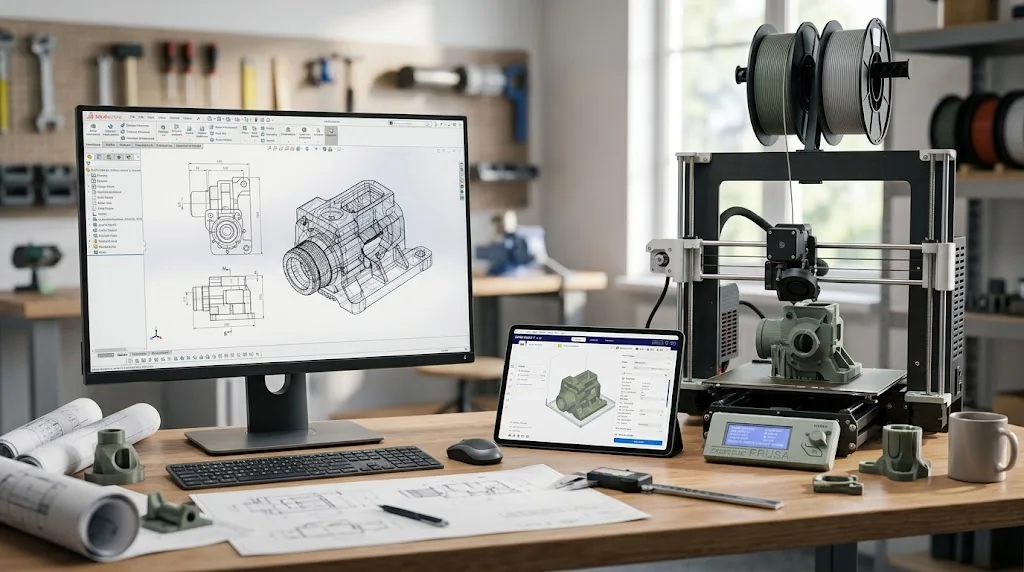
What Is The Difference Between CAD Software And 3d Printing Software? CAD software is used to create, edit, dimension, and control the 3D model. 3D printing software is used to prepare that model for a specific printer by slicing it into layers, adding supports, setting print parameters, and generating printer instructions.
CAD answers, “What should the part be?” Printing software answers, “How should the printer make it?” ProSoftStore helps buyers choose the right CAD tool before the model moves into slicing, printing, testing, and revision.
Quick Check
Compare CAD software for 3d printing at ProSoftStore before choosing a design tool for printable parts, prototypes, fixtures, and mechanical models.
What Is The Difference Between CAD Software And 3d Printing Software?
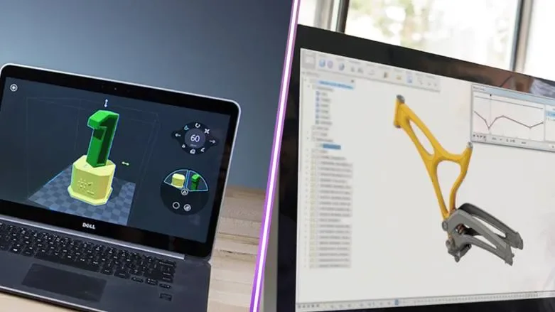
What Is The Difference Between CAD Software And 3d Printing Software? CAD software creates the model, while 3D printing software prepares that model for the printer. Autodesk describes CAD software as technology used to design in 2D or 3D, apply precise measurements, and generate documentation for manufacturing or construction. UltiMaker Cura is described as free and open-source slicing software, and PrusaSlicer is described as a slicer based on the original open-source Slic3r project.
| Workflow stage | CAD software | 3D printing software |
|---|---|---|
| Main job | Create and edit the 3D design | Prepare the design for printing |
| User question | What should the part look like and measure? | How should the printer build it? |
| Common tasks | Sketching, modeling, dimensions, constraints, assemblies | Slicing, supports, infill, layer height, temperature, printer profiles |
| Typical files | Native CAD, STEP, IGES, STL, 3MF, OBJ | Slicer project files, 3MF, G-code |
| Best for | Product design, mechanical parts, printable models | Printer setup, print preview, machine instructions |
| Revision control | Usually done in the CAD model | Usually not ideal for design revisions |
| Output | Editable model or export file | Printer-ready toolpath or G-code |
The simplest way to separate them is this: CAD software makes the object; 3D printing software tells the printer how to make the object.
CAD Software Creates The 3D Model
CAD software is where the design starts. It controls dimensions, shape, features, sketches, holes, walls, parts, assemblies, and sometimes drawings. A bracket, case, fixture, housing, connector, adapter, or prototype should usually be modeled in CAD first.
A good CAD model should be editable. If the hole spacing changes, the wall thickness needs adjustment, or a part no longer fits another component, the designer should update the CAD model rather than trying to patch the print file later.
Autodesk states that CAD tools can design in 2D or 3D, apply precise measurements, and generate documentation for manufacturing or construction. That is the core difference from slicer software: CAD controls the design source.
For buyers comparing low-cost design tools, the low-cost printable-part tool options article is useful because the right CAD choice depends on part complexity, accuracy, and editability.
3D Printing Software Prepares The Print
3D printing software is usually a slicer. It takes a model file and converts it into layers and printer instructions. UltiMaker says Cura has an open-source slicing engine and is free and open source. PrusaSlicer is also described as a slicer based on Slic3r, with tools for importing, slicing, and sending files to the printer.
A slicer controls print settings such as:
| Slicer setting | What it affects |
|---|---|
| Layer height | Surface quality and print time |
| Infill | Internal strength and material use |
| Supports | How overhangs are printed |
| Perimeters | Wall strength and surface structure |
| Temperature | Material flow and adhesion |
| Print speed | Quality, reliability, and time |
| Bed adhesion | First-layer stability |
| Orientation | Strength, surface finish, and support needs |
| Retraction | Stringing and nozzle behavior |
| G-code output | Printer motion and extrusion instructions |
A slicer is powerful, but it does not replace CAD. It can prepare a model for printing, but it should not be the main place to redesign the part.
Why CAD And Slicer Software Are Often Confused?
CAD software and 3D printing software are often confused because both appear in the same printing workflow. A beginner may download a model, open it in a slicer, change settings, and print it without using CAD at all. That can make it feel like the slicer is the main design tool.
The confusion becomes obvious when the model needs a real design change. If a mounting hole is wrong, a clip is too thin, or a case does not fit the electronics board, slicer settings cannot solve the design problem. The model needs to be corrected in CAD.
This is why ProSoftStore helps buyers compare 3d printing cad software by the design task, not just by the printer brand or slicer interface.
The Typical CAD-To-Print Workflow
A normal 3D printing workflow moves from CAD to slicer to printer. Each step has a different purpose.
| Step | Tool | Purpose |
|---|---|---|
| 1. Design the part | CAD software | Create accurate geometry |
| 2. Check the model | CAD or mesh repair tool | Confirm scale, walls, holes, and solid geometry |
| 3. Export the file | CAD software | Create STL, 3MF, OBJ, or another print-ready format |
| 4. Slice the model | 3D printing software | Convert the model into layers and print settings |
| 5. Preview the print | Slicer | Check supports, layer paths, and time estimate |
| 6. Print the part | Printer software or printer | Send G-code or machine instructions |
| 7. Test and revise | CAD software | Adjust the design source if the part fails |
A common mistake is revising only the exported STL file. If the design must change, go back to the CAD source file whenever possible.
CAD Software Handles Dimensions And Design Intent
CAD software is important when dimensions matter. If the printed part must fit screws, bearings, electronics, pipes, enclosures, brackets, or other parts, the designer needs control over exact sizes and relationships.
Parametric CAD is especially useful because dimensions can drive the model. FreeCAD describes itself as an open-source parametric 3D modeler made primarily to design real-life objects of any size, and its feature information says it can produce, edit, and export solid precise models for 3D printing, CNC machining, drawings, and other workflows.
For more context on modeling choices, the 3D modeling workflow decision factors can help buyers decide whether they need beginner modeling, parametric CAD, mechanical CAD, or visual modeling software.
3D Printing Software Handles Print Parameters
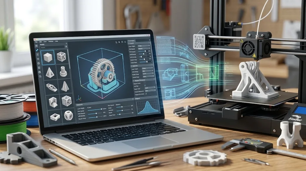
Slicer software controls how the printer builds the model. It does not decide what the part should be. It decides how thick each layer is, where supports go, how fast the nozzle moves, how much infill is used, and what machine instructions are generated.
For example, the same CAD model can be sliced in different ways:
| Print goal | Slicer adjustment |
|---|---|
| Faster print | Larger layer height, lower infill |
| Stronger part | More perimeters, higher infill, better orientation |
| Better surface | Smaller layer height, tuned speed |
| Less support material | Rotate model or adjust support settings |
| Better first layer | Bed adhesion, temperature, speed, leveling |
| Flexible material | Speed, retraction, temperature tuning |
| Resin printing | Supports, hollowing, drainage, exposure settings |
Slicer settings can improve a print, but they cannot turn a weak design into a good part if the CAD geometry is wrong.
File Types: CAD Files, STL, 3MF, OBJ, And G-Code
The difference between CAD and 3D printing software also shows up in file types. CAD files are editable design files. STL, 3MF, and OBJ are common export files used for printing or visualization. G-code is usually the printer instruction output from the slicer.
Autodesk Fusion help says Fusion can export for 3D printing to 3MF, STL, or OBJ, and Autodesk also notes that Fusion can export STL files for 3D printing workflows.
| File type | Usually created by | Main use |
|---|---|---|
| Native CAD file | CAD software | Editable design source |
| STEP / IGES | CAD software | CAD exchange between tools |
| STL | CAD software export | Common slicer input |
| 3MF | CAD or slicer | Model and print-related data |
| OBJ | CAD/modeling software | Mesh and visual model exchange |
| Slicer project | Slicer software | Print settings and arrangement |
| G-code | Slicer software | Printer instructions |
Keep the CAD source file. The exported STL or 3MF is usually not the best master file for future edits.
CAD Software For Simple 3D Prints
Simple prints may not require advanced CAD. A beginner making a name tag, small organizer, basic box, classroom model, or decorative object can often use beginner-friendly tools.
Tinkercad is a free web app for 3D design, electronics, and coding. That makes it useful for simple 3D modeling and first-time printing workflows.
However, simple tools can become limiting when the part needs exact dimensions, assemblies, threads, fit testing, mechanical revisions, or manufacturing drawings.
For buyers still learning CAD categories, the CAD category basics for practical users can help separate basic modeling from more structured CAD systems.
CAD Software For Functional 3D Prints
Functional prints require stronger design control. A clip, bracket, jig, mount, enclosure, hinge, adapter, or replacement part must usually fit something else. That requires measurement, tolerances, clearances, and revision control.
In functional printing, CAD is where the important design decisions happen. The slicer can help with strength and print quality, but the CAD model controls geometry.
Functional designs should consider:
| CAD design factor | Why it matters |
|---|---|
| Wall thickness | Affects strength and printability |
| Hole clearance | Controls screw and pin fit |
| Chamfers and fillets | Improves fit and reduces sharp edges |
| Orientation-aware geometry | Helps print strength |
| Tolerances | Controls assembly fit |
| Part separation | Supports printing and assembly |
| Revision history | Helps improve test prints |
| Source file control | Makes future edits easier |
For mechanical design context, the part-and-assembly CAD workflow helps explain why serious printed parts often need more than a mesh model.
CAD Software For 3D Printing And Product Design
A product design workflow may use 3D printing for prototypes, test fits, enclosures, brackets, fixtures, and early customer samples. In that workflow, CAD is the design source, while the slicer is the manufacturing-prep step for the printer.
If a prototype fails, the designer should return to CAD, revise the model, export again, slice again, and print another test. This keeps the design history clean.
For buyers comparing imported-model editing and preparation, the geometry cleanup before downstream use is useful. A printable file may need repair or simplification before it becomes useful in the next workflow.
CAD Software Vs Mesh Editing Software
Some 3D printing workflows use mesh editing tools. Mesh editing is useful for downloaded STL files, scans, sculpted models, organic shapes, and artistic objects. CAD is usually better for dimensioned parts, mechanical geometry, and controlled revisions.
The key difference is design control. CAD files often preserve sketches, features, dimensions, constraints, or parameters. Mesh files usually represent surfaces as triangles. That can be fine for printing, but it can make exact design edits harder.
A mesh editor may be enough for a decorative model. A CAD system is usually better for a replacement part, mounting fixture, mechanical prototype, or product enclosure.
Slicer Software Cannot Replace CAD
A slicer can scale, rotate, mirror, duplicate, arrange, support, and prepare a model. Some slicers also include repair or basic editing tools. But slicer edits are usually not a substitute for CAD design.
A slicer is not ideal for changing design intent. If the wall is too thin, the snap-fit is wrong, or the hole spacing is incorrect, the right fix usually belongs in CAD.
For users who assume a printer includes everything needed for design, the included printer software scope helps clarify why printer packages often include slicing and setup tools rather than full CAD design capability.
CAD Software Cannot Replace Slicer Software
The reverse is also true: CAD software usually cannot replace slicer software. CAD can export a model, but the printer still needs layer-by-layer preparation, material settings, support generation, print preview, and machine-specific instructions.
Some CAD tools include print-preparation features or can send models to a slicer, but the slicing step still matters. Autodesk Fusion help, for example, describes options to export to 3MF, STL, or OBJ and send to an installed 3D printing application.
The right workflow uses both tools: CAD for design, slicer for printing.
CAD Software For Engineering Prints
Engineering prints need accuracy. A fixture, adapter, tool holder, test part, jig, enclosure, prototype, or replacement part must often fit real hardware. That makes CAD software more important than slicer settings.
Engineering users should prioritize CAD features such as:
| CAD feature | Why it helps |
|---|---|
| Real units | Keeps dimensions consistent |
| Constraints | Controls sketch behavior |
| Parametric edits | Makes revisions faster |
| Assemblies | Tests part fit |
| Section views | Helps inspect internal geometry |
| Export controls | Improves print file quality |
| Drawings | Supports documentation |
| Version management | Tracks design changes |
For advanced CAD needs, the high-control engineering CAD indicators can help buyers decide when a stronger CAD platform is justified.
CAD Software For Architecture And Presentation Prints
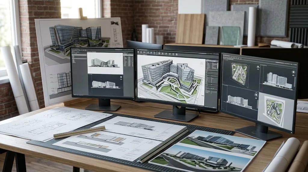
Architectural 3D prints may come from CAD, BIM, or visual modeling tools. The CAD side defines walls, openings, massing, site context, or details. The slicer prepares the physical model for printing.
For architecture, the model may need simplification before printing. Thin walls, small mullions, unsupported details, or complex interiors may not print cleanly at small scale.
For building-focused software context, the building design documentation route helps buyers understand how design documents, models, and presentation outputs differ. The visual modeling and drafting workflow split also helps separate presentation modeling from technical drawing workflows.
CAD Software For Construction 3D Prints
Construction teams may use 3D printing for site models, coordination studies, presentation models, prototype components, formwork ideas, or custom fixtures. The design still needs to be created or simplified before it reaches the slicer.
A construction print may not need the same precision as a functional machine part, but it still needs clean geometry. Scale, wall thickness, simplified detail, and clear output purpose matter.
For construction-focused buyers, the construction design output checklist can help define whether the priority is drawing documentation, 3D modeling, BIM-style coordination, or presentation output.
CAD Software For Manufacturing And CNC
CAD and 3D printing software are also different from CAM software. CAD creates the model. Slicer software prepares additive printing. CAM software prepares subtractive machining such as milling, turning, routing, wire EDM, or mill-turn operations.
Mastercam describes its CAD/CAM software as covering CNC machining operations including milling, turning, 5-axis machining, mill-turn, Swiss machining, wire EDM, and router programming. That is a different workflow from slicing a model for a 3D printer.
For manufacturing context, the additive and subtractive preparation contrast helps buyers understand why 3D printer slicing and CNC programming are related production steps but not the same software category.
CAD Software And Technical Analysis
CAD software creates the geometry, but engineering analysis may require separate tools. A model can be printed for testing, but simulations, calculations, and performance analysis may happen before or after the print.
A printed prototype can show fit and physical behavior, but it does not replace proper analysis when stress, heat, fluid flow, motion, or control systems matter.
For engineering software roles, the calculation environment and CAD model roles article helps separate technical computing, CAD modeling, and design documentation.
CAD Software And Drawing Documentation
3D printing workflows do not always need formal drawings, but professional workflows often do. A drawing can record part name, material, revision, dimensions, tolerances, finish, scale, and approval information.
This matters when printed parts are used for customers, prototypes, jigs, fixtures, or production references. The CAD model creates the part; the drawing explains the part.
For documentation setup, the drawing layout and title data workflow can help connect printable part design with professional sheet control.
CAD Software Cost Vs 3D Printing Software Cost
CAD software and 3D printing software can have very different cost structures. Some CAD tools are free or have personal-use plans. Some professional CAD tools require subscriptions. Many slicers are free, open source, or printer-bundled.
FreeCAD is free and open source. Tinkercad is a free web app. Autodesk says Fusion personal use remains available for home-based, non-commercial design, manufacturing, and fabrication projects, while still allowing 3D printing workflows such as STL export. Onshape offers a Free plan for non-commercial projects, but public documents matter for privacy.
For purchase planning, the CAD pricing and workflow cost factors can help buyers compare license cost, training time, commercial rights, export limits, and project needs.
How Many Tools Do You Need?
A beginner may only need one CAD tool and one slicer. A professional workflow may need several tools: parametric CAD, mesh repair, slicer, printer management, drawing software, simulation software, and sometimes CAM.
A typical maker workflow might be:
| User type | Likely software stack |
|---|---|
| Beginner | Tinkercad + slicer |
| Hobby maker | FreeCAD or Fusion Personal + slicer |
| Open-source hardware builder | FreeCAD or Onshape Free + slicer |
| Product designer | Professional CAD + slicer + rendering |
| Mechanical engineer | Parametric CAD + simulation + slicer |
| Print farm user | CAD source + production slicer profiles |
| Manufacturer | CAD + CAM + slicer + documentation tools |
For broader market context, the CAD software variety and use cases can help explain why no single tool covers every workflow equally well.
Common Mistakes In CAD-To-Print Workflows
Most printing problems begin before the print starts. Weak CAD setup, wrong export settings, poor scale control, bad wall thickness, and incomplete model checks can create print failures.
Common mistakes include:
| Mistake | Better approach |
|---|---|
| Designing only in the slicer | Create the part in CAD first |
| Editing only STL files | Keep the editable CAD source |
| Ignoring wall thickness | Design for the printer and material |
| Using the wrong units | Check scale before slicing |
| Exporting too coarsely | Use appropriate mesh settings |
| Trusting auto-repair only | Fix the model source where possible |
| Forgetting tolerances | Add clearance for real printed fit |
| Treating CAD and slicer as one tool | Use each tool for its proper role |
A successful print workflow starts with a good model, then uses the slicer to prepare that model intelligently.
How To Choose CAD Software For 3D Printing?
Choose CAD software by the part you need to design. A simple shape does not need the same tool as a mechanical prototype. A decorative object does not need the same CAD workflow as a dimensioned fixture.
| If you need to print | Choose CAD that supports |
|---|---|
| Basic shapes | Simple 3D modeling |
| Replacement parts | Accurate measurement and dimensions |
| Enclosures | Parametric features and assemblies |
| Prototypes | Iteration and export control |
| Mechanical fixtures | Constraints, tolerances, drawings |
| Decorative models | Sculpting or mesh modeling |
| Architecture models | Scale and model simplification |
| Commercial products | Strong CAD control and licensing |
If the part must fit, move, carry load, or be revised, CAD quality matters more than the slicer brand.
How To Choose 3D Printing Software?
Choose 3D printing software by the printer, material, and desired print quality. The slicer should support your printer profile, filament or resin type, support strategy, print preview, and output method.
| If you need | Check in the slicer |
|---|---|
| Reliable first layers | Bed adhesion and calibration tools |
| Strong functional parts | Perimeters, infill, orientation settings |
| Clean overhangs | Support controls |
| Faster prints | Speed and layer-height control |
| Multiple materials | Multi-material support |
| Print farms | Printer management workflow |
| Resin printing | Exposure, supports, hollowing, drainage |
| Better troubleshooting | Preview, estimates, and profile control |
The best slicer is the one that prepares the model reliably for your specific printer and material.
How ProSoftStore Helps Buyers Choose?
What Is The Difference Between CAD Software And 3d Printing Software? CAD software creates and controls the design. 3D printing software prepares that design for the printer. CAD is where dimensions, geometry, features, assemblies, and revisions belong. Slicer software is where layers, supports, infill, temperatures, print orientation, and printer instructions belong.
ProSoftStore helps buyers compare CAD software by output: printable models, mechanical parts, fixtures, prototypes, 3D design files, drawings, construction models, and manufacturing workflows. That keeps the software decision tied to the work the user actually needs to complete.
If your team needs accurate printable models before slicing and printing, ProSoftStore can help you compare cad software for 3d printing and choose a CAD license that fits your design workflow.
FAQs
What Is The Difference Between CAD Software And 3d Printing Software?
CAD software is used to create and edit the design model. 3D printing software is used to prepare that model for the printer. CAD controls dimensions, geometry, features, and design revisions. 3D printing software slices the model into layers, creates supports, applies print settings, and generates printer instructions.
Is CAD software the same as slicer software?
No. CAD software and slicer software are different. CAD software creates the part model. Slicer software prepares the model for the printer. UltiMaker Cura is described as free and open-source slicing software, while CAD software such as AutoCAD and Fusion is used for 2D or 3D design, measurements, and documentation.
Do I need CAD software for 3D printing?
You need CAD software if you want to create or edit your own model. If you only download existing STL or 3MF files, you may only need a slicer. However, if you need to change dimensions, create a replacement part, design an enclosure, or build a functional prototype, CAD software is the better place to make those changes.
Can a slicer fix a bad CAD model?
A slicer can sometimes repair minor mesh issues, add supports, change orientation, or scale a model, but it should not be used as a replacement for proper CAD design. If a model has wrong dimensions, weak geometry, missing clearance, or poor wall thickness, the better fix is usually in CAD.
What files move from CAD software to 3D printing software?
Common files include STL, 3MF, and OBJ. Autodesk Fusion help says Fusion can export designs for 3D printing to 3MF, STL, or OBJ. Keep the original CAD file as the editable source, then export a print file for the slicer.
Is FreeCAD CAD software or 3D printing software?
FreeCAD is CAD software, not slicer software. FreeCAD describes itself as an open-source parametric 3D modeler made primarily to design real-life objects of any size, and its features include producing, editing, and exporting precise models for 3D printing, CNC machining, drawings, and other workflows.
Is Cura CAD software or 3D printing software?
Cura is 3D printing software, specifically slicing software. UltiMaker says Cura has an open-source slicing engine and is free and open source. Cura prepares models for printing, but it is not the main tool for creating dimension-controlled CAD designs.
What should I buy first, CAD software or 3D printing software?
Start with the design problem. If you need to create your own parts, choose CAD software first, then pair it with a slicer that supports your printer. If you only print downloaded models, the slicer may be enough. For serious product design, replacement parts, mechanical prototypes, or custom fixtures, CAD software is the foundation.